
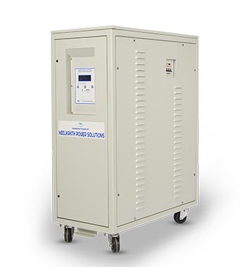
Automatic Power Factor Correction
Most of the industrial and Commercials installations have large variables inductive severe loads such as motors, CNC Machines, Air conditioners, Variable Frequency Drives, Thyristor Drives, etc. This results in lagging of Power factor. This means loss and wastage of Electrical resources and heavy Penalties by Electricity Board. In some cases such as fixed load system, manually operated capacitor banks are used but this is not correct solutions because chances of Switching ON and OFF are done by Operator.
However in case of rapidly varying and scattered loads it becomes difficult to maintain a high power factor by manually switching on/off the capacitors in proportion to variation of load within an installation. This drawback is overcome by using an APFC panel (Automatic Power Factor Correction Panel) which not only maintains a power factor but also eliminates the need for constant manual interference
| Rating | 30 – 1200 KVAR |
| Steps | 2 / 3 / 5 / 6 / 10 / 12.5 / 20 / 25 / 30 / 40 / 50 / 60 / 75 / 80 KVAR |
| Sensing | Single / Three CT Sensing. |
| PF Controller | LCD Display for PF. LCD Display for PF & Power Parameters. |
| Incomer | MCCB / ACB for Over load and short circuit protection. |
| Each Step Protection | 1)HRC Fuse 2)MCB / MCCB |
| Detune Reactors Copper / Aluminum | 1)Without 2) 1 % 3) 5.6 % 4) 7 % 5) 14 % |
| Capacitors MPP / Gas Field / APP | 1)440 Volts. 2)525 Volts. 3)690 Volts |
| Contactor Switch | 1)Capacitor duty contactor. 2)AC 3 Duty Contactor. 3)With Early make contact |
| Communication | RS 485 / RS 232 Optional. |
- Step switching using Contactor Switching.
- Reduction of voltage flickering.
- Enhances capacity of Transformer, Local generator systems such as Diesel and windmill generator.
- Saves energy by reduced max. Demand, PF bonus & saving in Transformer losses.
- Accurate Power Factor control, even in the presence of Harmonics.
- Dramatically increases the life expectancy of switching elements and capacitor.
- Built-in network analyzer, measuring all network parameter including harmonics.
- Modular and up gradable with increased plant load.
- Detuned systems that detune the network to prevent resonance and absorb harmonics.
- Ammeter for Load Current.
- Input Under and Over Voltage indication and Cut off
- Electronics Output Over Load.
- Ground Fault Monitoring with Trip and Indication / Earth leakage.
- Surge Suppressor (Metal Oxide Varistor)
- Surge Protective Device 8/20 micro sec. as per IEC 61000-4-4 / 61000-4-5.
- Stabiliser By pass Switch
- Auto Start with time delay.
Typical schematics for product installation
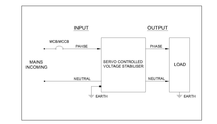
- # Non-Standard KVA, Input Voltage Range and Output Voltages are also available on request.
- # NEELKANTH reserves the rights to amend design and specification without notice as continuous efforts are Made to Improve product performance.
- # Some of the features are optional depend on model and as per order.
| Type | KVA Ratings | Model | Servo Motor | Input Voltage Range (VAC) |
Output Voltage (VAC) |
|---|---|---|---|---|---|
| Single Phase | 1 – 100KVA | SD – XXX SA – XXX |
PMDC / AC Synchronous |
170 - 270 | 230 |
a) Please contact our sales and application engineers for further guidance
b) Non-Standard Input Voltage Range and Output Voltages are also available on request
- Medical Diagnostic Equipment
- Electronic Equipment
- Lab Equipment
- Pharmaceuticals Machine
- Textile Machinery
- Process Controls
- Elevators
- Cold Storage
- Hospitals
- Residential